Saturday, May 14, 2011

The 555 inductance meter enhanced edition

I know it's been a long time since my last blog post, but I had to decrease the level of entropy on my lab desk.
Anyway, I managed to get some projects done, so I can blog them in the next weeks!
Here is the first one: An improved version of my 555 inductance meter!
At virtually no cost (at least if you have some basic parts on stock), you can improve the performance under different serial resistances of the measured inductors.
You just have to add a second NE555 and a few resistors.
The mayor problem of the old version is the rather big output change when the serial resistance changes.
If you have a too big serial resistance, the amplitude of the LC-oscillators flattens out and you aren't measuring the frequency any more. You'll get readings like this:


I simulated these waveforms by stepping the serial resistance from 0.1 ohm (green line on the bottom) to 10 ohm (pink line on the top). The steps are 1 ohm each.

If you now amplify the sine wave to a rail-to-rail rectangle by using a comparator or a schmitt-trigger, you can use this signal as a basis for the low-passed output.
Here is the new schematic:

The output of this version looks like this:

In reality, my inductors had serial resistance from 0.01 to about 3 ohm.
The new version is really better at differing between resistance and inductance,
so at a cost of about 2€ for the basic design and additional 1€ for the improvement,
it might be the cheapest inductance meter out there!
Build yourself one I you don't have one, you won't regret it!

Apexys

Friday, March 25, 2011

Two important C# code snippets

Hi everyone!
And this time especially the AX-team of our little contest!

Here are the two last APXD-snippets in C# :

Converting from a String like '10001000' to an int (this would be 136):

int getint(String bin) {
  int result = 0;
  for(int i = 0; i< 8; i++){
   if(bin[i] == '1'){
    result +=(int) Math.Pow (2,7-i);
   }
  }
  return result;
}


Converting from an int like 136 to the binary-String:

String getbin(int input) {
   String result = "";
   int ax;
   for (int i = 0; i < 8; i++) {
    ax = (int)Math.Pow(2, 7 - i);
    if (input >= ax) {
     result += "1";
     input -=ax;
    }
    else {
     result += "0";
    } 
   }
  return result;
}


That's all for the moment!
Have a good weekend!

apexys

Monday, March 7, 2011

Overdrive and distortion

Hi!

Whilst doing audio stuff, at some point I got to the point, where I wanted to modify the sound of my instrument.
There are two mayor types of distorting an instrument: overdrive and distortion.

Overdrive is the older sound.
Back when there were people building amplifiers out of glass valves and operating with high voltages,
the amplifiers couldn't handle all the voltages over the input range.
This meant, starting at a certain point, the signal would start to clip.
Add some harmonic signals and some white noise,
which both are characteristic for tube amplifiers, and you get overdrive.
Personally, I don't really like overdrive.
It sounds too dirty and noisy,
but in some settings and genres like hard rock, it sounds really great.
The easiest way to get a mean overdrive this days is to use opamps.
Simply configure one as a non-inverting-amplifier with rather high amplification factor and use high input voltages.
For best retro-sound, use a JFET one (as the TL072). But even the LM324 will work.
Here is a schematic for an overdrive with an opamp per channel:


And this is, how the signal looks like:

Now to the other possibility of generating a sound effect by simply clipping it: distortion.
Distortion means that you generate the clipping effect in a much more controllable way, means by diodes.
Diodes have a U/I curve with a kink at normally around 0.8V. This means, they start leading when signals higher than this kink are applied.
An easy way to use this kink for distortion is the following schematic:
And again an example of the waveform.

In this example, I wanted very strong distortion.
With the distortion-type distortion (not the overdrive one), there is an easier approach to this.
Just use the opamp as an schmitt-trigger:

Notice the small difference in the waveform, compared to the solution with the diode:

This was my small walkthrough through these kinds of distortion systems.
Thank you for reading and until next time!

apexys

Sunday, February 27, 2011

The NE556 based Theremin

This is my second entry for the 555 contest.

It is the famous instrument, the theremin in a 556-based version.
I had to overclock the timer to about 4Mhz and it works!
This is pretty cool since the timer has a maximum frequency of about  200kHz.
This is the schematic:


The two 555 cores of the NE556 work both as rectangle oszillators.
The frequency of the second one is altered by my body frequency.
Now both signals are mixed in the middle and amplified via Q1.
An earplug makes it hearable.

This is what the signal looks like:


It is basically HF with some NF modulated on it. AM. Like in the radio.
In LTSpiceIV, you can simulate a sound output and play it in real life!
Simply add the SPICE directive .wave C:\waveout.wav 16 44100 V(n010) to your simulation file.
What it does is:
It generates a .wav-file with 16 bit resolution and 44,1kHz samplerate in C:\waveout.wav that sounds exactly like the voltage on node 10.
Here is a sound example of this schematic.

Now, I etched a DCB in my standard procedure.


The lower pad left is the pad to put your hand on. Then move the other hand over the big upper ground plane.
Resistors were the first parts to be populated.


Now the timing caps followed.
At first, I wanted to use 1206 54pF caps but they didn't fit. Well, the dangers of a self drawn board I assume. As a replacement, two 20pF caps in 0805 on every side came to the rescue.
The two bars on the right side act as a cap bench. I do this on lot of my circuits: First I just solder in a 100nF ceramic capacitor and if it is not sufficient, I solder in other caps. In this particular case, I soldered in quite a few caps. Starting from the upper border: 270pF x2, 100nF x2, 800nF x2, 1µF.


After having done this, some silicon followed:


Then the NE556 and some other stuff and it's all ready to use!


It is really difficult to play specified tones on this thing.
I end up most of the times getting WEEEH-UUUUH-WEEEEH-UUUUUH sounds.
But hey, it works!
Here is a prove:


What do you think of it?
As usual, you can download the simulation file here.

Apexys

Wednesday, February 23, 2011

The NE555 based inductivty meter

Hi!
This blog is about my new inductivity meter based on a NE555.
For my experiments with switch mode converters, I needed a simple way to compare inductivities of coils.
Since I don't have a multimeter which can do inductivity measurement (but I have a really great multimeter, more infos perhaps in the next blog), I decided to build one.

And this is the schematic of it:


A NE555 works in its most simple rectangle osciallation configuration.
In this mode, the duty-cycle should be around 50%, but this depends on the load on pin 3.
Over the amplifying transistor Q1 the AC is given on an LC circuit.
It oscillates a freqency given by the equation:


This oscillating waves are amplified by Q2 and frequency is converted into a voltage by the RC-network of C3 and the ampmeter.
Due to the capacity of both C3 and C2 being constant, the current through the ampmeter is defined by the inductivity.
Here is a simulated image of what should happen:
Green is 100µH, blue 200µH, red 300µH and so on.
Here is a more entertaining version of it:

Well, that's the concept, let's go to the build!
Here is a image of the DPB (Drawn Circuit Board):

I had to make a capacitor bench out of the one capacitor because my supplier didn't have ceramic 10µF caps. Electrolytic capacitors are a pain in the ass and should only be used to stabilize the power supply.
 After drawing this to a piece of copper-cladded FR4 board material, I dried it using a diy-hotplate: the glass cover of a halogen desk lamp.
Now I heated up the etching solution (Sodium persulfate):
 It is the most easy way to do a board fast and with diy-methods. No big technical machinery, just a gas flame and an erlenmeyer flask.
Maybe I should have cleaned it before taking this image, but it's clean from the inside.
You can easily determine when the liquid is hot enough:
It starts to have a small layer of steam on it.
Here is a image of the board in the etching bath.
I takes about an hour on room temperature and about 20 minutes with the heating procedure.

After all the unwanted copper dissolved, I took it out of it's bath and it looked like this:


Now I used ethanol to wash of the ink.
Acetone helped me at the edges:


Well, time to get it populated!
If you are using lead-free solder, you should tin it first.
Since I'm using lead-containing solder,I had no problem soldering everything on:


The "thing" that's holding it is a third hand.
I think it is in fact the most helpful object whilst soldering.
If you don't have one, get one!
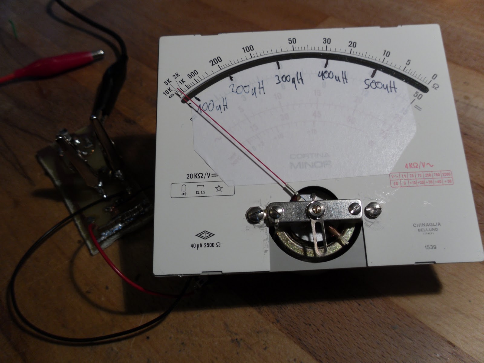
I "recycled" an old analog multimeter to get a nice µA-meter:


So, this is how it looks like with everything on it:

Now, testing time!


The inductivity used is this one:


How do you like it?
I think it's a cool little gadget, saving time and money!
You can download the LTSpice file here.
Have a good time!
apexys

Monday, January 31, 2011

Epad 10.2 review

Hi there!
it's time to review my newest gadget: the Android Epad 10.2"

As the name says, it is a iPad-clone with a slightly bigger screen (10.2") and running Android 2.1.
Here is a image of how it looks like in the commercial:


And here is another image of it, take with my digital camera: 


It is pretty hard to get it on camera, but this is, how the home screen looks like.
The Epad has a 1GHz ARM processor like the iPad, but it has a resistive touchscreen with 1024x600 pixels resolution, but unlike the iPad, it can be used with a pen or gloves.

 Here are some photos of the interfaces:


The internet connectivity is done via WiFi or an external USB surf stick.
It has two gigabytes of internal NAND flash and can use TransFlash aka µSD cards.
The PC data connection is done with a mini-USB cable, here called OTG.
You can charge the internal LiIon accumulator by applying 9VDC to the DC-terminal or simply using the included charger.
I was surprised by the rather high audio quality of the 3.5 mm output, even though the internal speakers are crap.  
You can connect it to a LAN with the included adapter, which looks like this:


The operating system is Android 2.1.
I like it, being small and fast.
It loads almost every website, even though it can't do every kind of script.
You can use it to view videos on YouTube, to watch DVDs (even via an external USB DVD drive!) or blogging on BlogSpot, as I'm doing now.

The virtual keyboard is a bit hard to use (You have to leave your hand some milimeters above the touchscreen and pull down the fingers separately), but you can use an USB keyboard.
If you want to exchange data without using a mini-USB cable, just do it using a µSD card. 

Some applications some exist in the Android Market, some you have to code on your own.
But hey, the Android SDK is free, so ain't it a great platform for mobile hacking?
I just need a compiler that runs directly on it.

You can pick these tablets up on ebay for about 200€ for a brand-new one or find it for the same price in other internet stores.
  
Finally, I would say, it's really a great gadget with much functionality for low price.

 I hope you liked this review!
/apexys/01312011/1921  

Sunday, January 23, 2011

AVRTimerCalculator - JAVA-version

Hi!
Here comes the requested JAVA-version of the AVRTimerCalculator.


You can download it here.
Share and enjoy ;-)
/apexys/01232011/1622