Computers are one of the most important parts of our every day life.
Not only that we actively use them to do things like communicate, entertain,
educate or blog, as I am currently doing, they also control the transport of goods,
they help emergency teams to rescue people in danger and do a lot more.
But what would happen, if, someday in the future, our economy will break?
No more cheap parts from China, no more cheap microprocessors, no more cheap computers.
We would definitely have a really big problem.
But not only the possible breakdown of the economic system is a reason for me to do this project.
I also want to learn, how a processor REALLY works.
Yes, it uses logic gates, it uses a synchronous design and so on.
But how would I build a computer, if I were to do so my self?
This is, what this series of blogs will be about.
It is definitely planned as a long-time project,
so I will interrupt the series for updates on other projects.
So, what will this first blog be about?
Well, we need to define, what the computer will be able to do.
I will restrict this on only the instructions and the main build.
So, what will our system look like?
Mostly like this:
Simple and easy.
So, now we just need the mentioned 16 instructions mentioned in the ALU.
Guess what the next blog will be about.
In my LED-matrix-project, I needed some kind of possibility to display text.
Since the flash memory of an AVR, especially from the ATTiny series, is somewhat limited,
I had to find a good way to store the characters without using up to much of the space.
After a small discussion on www.mikrocontroller.net, I had everything I needed to make it.
Well, everything but the font.
As recommended, I'm using a 16-bit mono-color font, which means, I'm storing all the information needed in just two bytes. This makes it a bit hard to understand by just looking at the binary, so I wrote a small program
to generate the chars for me.
Using this and a routine from the forum-user "Peter Dannegger", I can now display the characters on the matrix. Here is the function, which is meant to be used together with the code I posted earlier:
void writeSign(uint8_t px, uint8_t py, uint16_t pattern, uint8_t color){ for (int x = 0; x < 3; x++) { for (int y = 0; y < 5; y++) { if (pattern & 1) // LSB first
ht1632_plot(px +x, py +y, color); else
ht1632_plot(px +x, py +y, BLACK);
pattern >>= 1; // next bit
}
}
}
Hi!
I've been looking quite a while for cheap LED matrices now and I finally found some.
SureElectronics has some really good ones, in all variants you could want.
Finally, I bought two DE-DP14211 matrices.
Featuring a 32x16 tricolor LED matrix, 4-bit PWM dimming and a SPI-like interface, they only cost about 25€ per item.
Well, I bought them without reading the datasheet, because what was named SPI-like was different enough from normal SPI, that you couldn't use the AVRs hardware SPI to control these devices.
After googling the misery, I found an Arduino library that could control the matrix.
Now, since I'm not using the Arduino bootloader, I had to change a few things.
First of all, you need to pick the functions, you need.
In my case, I only wanted the parts to be able to set or delete a pixel.
So what did I need?
First of all, go through the compiler definitions.
We won't use the DEBUGPRINT function, so don't copy it.
Here is what you need:
/* * commands written to the chip consist of a 3 bit "ID", followed by * either 9 bits of "Command code" or 7 bits of address + 4 bits of data. */ #define HT1632_ID_CMD 4 /* ID = 100 - Commands */ #define HT1632_ID_RD 6 /* ID = 110 - Read RAM */ #define HT1632_ID_WR 5 /* ID = 101 - Write RAM */ #define HT1632_CMD_SYSDIS 0x00 /* CMD= 0000-0000-x Turn off oscil */ #define HT1632_CMD_SYSON 0x01 /* CMD= 0000-0001-x Enable system oscil */ #define HT1632_CMD_LEDOFF 0x02 /* CMD= 0000-0010-x LED duty cycle gen off */ #define HT1632_CMD_LEDON 0x03 /* CMD= 0000-0011-x LEDs ON */ #define HT1632_CMD_BLOFF 0x08 /* CMD= 0000-1000-x Blink ON */ #define HT1632_CMD_BLON 0x09 /* CMD= 0000-1001-x Blink Off */ #define HT1632_CMD_SLVMD 0x10 /* CMD= 0001-0xxx-x Slave Mode */ #define HT1632_CMD_MSTMD 0x18 /* CMD= 0001-10xx-x Use on-chip clock */ #define HT1632_CMD_EXTCLK 0x1C /* CMD= 0001-11xx-x Use external clock */ #define HT1632_CMD_COMS00 0x20 /* CMD= 0010-ABxx-x commons options */ #define HT1632_CMD_COMS01 0x24 /* CMD= 0010-ABxx-x commons options */ #define HT1632_CMD_COMS10 0x28 /* CMD= 0010-ABxx-x commons options */ #define HT1632_CMD_COMS11 0x2C /* CMD= 0010-ABxx-x commons options */ #define HT1632_CMD_PWM 0xA0 /* CMD= 101x-PPPP-x PWM duty cycle */
// Dual 3216 LED Matrix // If you have only one set these to: // X_MAX=31 // Y_MAX=15 // CHIP_MAX=4 #define X_MAX 63 // 0 based X #define Y_MAX 15 // 0 based Y #define CHIP_MAX 4*2 // Number of HT1632C Chips // 4 each board * 2 boards // possible values for a pixel; #define BLACK 0 #define GREEN 1 #define RED 2 #define ORANGE 3
#define calcBit(y) (8>>(y&3))
Next is the variable definition: /* * Set these constants to the values of the pins connected to the SureElectronics Module */ static const byte ht1632_data = 53; // Data pin (pin 7) static const byte ht1632_clk = 52; // Data pin (pin 2) static const byte ht1632_wrclk = 51; // Write clock pin (pin 5) static const byte ht1632_cs = 50; // Chip Select (pin 1) // The should be a common GND. // The module with all LEDs like draws about 200mA, // which makes it PROBABLY powerable via Arduino +5V //(Apexys comment: The module will draw up to 1.5 Amps with all LEDs on, // so forget about powering it with an Arduino and get it a good // switching PSU!) /* * we keep a copy of the display controller contents so that we can * know which bits are on without having to (slowly) read the device. * Note that we only use the low four bits of the shadow ram, since * we're shadowing 4-bit memory. This makes things faster, but we * COULD do something with the other half of our bytes ! */ byte ht1632_shadowram[63][CHIP_MAX] = {0};
Followed by the functions
void OutputCLK_Pulse(void) //Output a clock pulse void ht1632_chipselect(int select) //Select a chip void ht1632_writebits (byte bits, byte firstbit) //Write bits on SPI static void ht1632_sendcmd (byte chipNo, byte command) Send Command static void ht1632_senddata (byte chipNo, byte address, byte data) //Data void ht1632_clear() //Clear Display byte xyToIndex(byte x, byte y) //Get RAM position for a pixel int get_pixel(byte x, byte y) //Get a pixel's color at a position void ht1632_plot (byte x, byte y, byte color) //Set a pixel static void ht1632_initialize() //Init the display
Now, simply replace byte with uint8_t. Two last things are to do: You need to define four pins of any port as output and you need a function to replace the digitalWrite function of the Arduino library. Here it is:
Hi!
This is the second one of my promised series of blog post!
It's about a little experiment I did some weeks ago.
I wanted to cover iron stick with liquid iron sulfide,
so I could bring a nice layer of sulfur on some copper in an electrolysis.
To have some fun, I added the thermite process to the sulfurisation.
Here is how it looked like:
Well, quite impressive.
I didn't use the iron sulfide, but gave it to my friend C3H5N3O9 so he could make his copper-sulfur-plate.
I hope you liked this non-electronics-related experiment.
I know it's been a long time since my last blog post, but I had to decrease the level of entropy on my lab desk.
Anyway, I managed to get some projects done, so I can blog them in the next weeks!
Here is the first one: An improved version of my 555 inductance meter!
At virtually no cost (at least if you have some basic parts on stock), you can improve the performance under different serial resistances of the measured inductors.
You just have to add a second NE555 and a few resistors.
The mayor problem of the old version is the rather big output change when the serial resistance changes.
If you have a too big serial resistance, the amplitude of the LC-oscillators flattens out and you aren't measuring the frequency any more. You'll get readings like this:
I simulated these waveforms by stepping the serial resistance from 0.1 ohm (green line on the bottom) to 10 ohm (pink line on the top). The steps are 1 ohm each.
If you now amplify the sine wave to a rail-to-rail rectangle by using a comparator or a schmitt-trigger, you can use this signal as a basis for the low-passed output.
Here is the new schematic:
The output of this version looks like this:
In reality, my inductors had serial resistance from 0.01 to about 3 ohm.
The new version is really better at differing between resistance and inductance,
so at a cost of about 2€ for the basic design and additional 1€ for the improvement,
it might be the cheapest inductance meter out there!
Build yourself one I you don't have one, you won't regret it!
Whilst doing audio stuff, at some point I got to the point, where I wanted to modify the sound of my instrument.
There are two mayor types of distorting an instrument: overdrive and distortion.
Overdrive is the older sound.
Back when there were people building amplifiers out of glass valves and operating with high voltages,
the amplifiers couldn't handle all the voltages over the input range.
This meant, starting at a certain point, the signal would start to clip.
Add some harmonic signals and some white noise,
which both are characteristic for tube amplifiers, and you get overdrive.
Personally, I don't really like overdrive.
It sounds too dirty and noisy,
but in some settings and genres like hard rock, it sounds really great.
The easiest way to get a mean overdrive this days is to use opamps.
Simply configure one as a non-inverting-amplifier with rather high amplification factor and use high input voltages.
For best retro-sound, use a JFET one (as the TL072). But even the LM324 will work.
Here is a schematic for an overdrive with an opamp per channel:
And this is, how the signal looks like:
Now to the other possibility of generating a sound effect by simply clipping it: distortion.
Distortion means that you generate the clipping effect in a much more controllable way, means by diodes.
Diodes have a U/I curve with a kink at normally around 0.8V. This means, they start leading when signals higher than this kink are applied.
An easy way to use this kink for distortion is the following schematic:
And again an example of the waveform.
In this example, I wanted very strong distortion.
With the distortion-type distortion (not the overdrive one), there is an easier approach to this.
Just use the opamp as an schmitt-trigger:
Notice the small difference in the waveform, compared to the solution with the diode:
This was my small walkthrough through these kinds of distortion systems.
Thank you for reading and until next time!
It is the famous instrument, the theremin in a 556-based version.
I had to overclock the timer to about 4Mhz and it works!
This is pretty cool since the timer has a maximum frequency of about 200kHz.
This is the schematic:
The two 555 cores of the NE556 work both as rectangle oszillators.
The frequency of the second one is altered by my body frequency.
Now both signals are mixed in the middle and amplified via Q1.
An earplug makes it hearable.
This is what the signal looks like:
It is basically HF with some NF modulated on it. AM. Like in the radio.
In LTSpiceIV, you can simulate a sound output and play it in real life!
Simply add the SPICE directive .wave C:\waveout.wav 16 44100 V(n010) to your simulation file.
What it does is:
It generates a .wav-file with 16 bit resolution and 44,1kHz samplerate in C:\waveout.wav that sounds exactly like the voltage on node 10. Here is a sound example of this schematic.
Now, I etched a DCB in my standard procedure.
The lower pad left is the pad to put your hand on. Then move the other hand over the big upper ground plane.
Resistors were the first parts to be populated.
Now the timing caps followed.
At first, I wanted to use 1206 54pF caps but they didn't fit. Well, the dangers of a self drawn board I assume. As a replacement, two 20pF caps in 0805 on every side came to the rescue.
The two bars on the right side act as a cap bench. I do this on lot of my circuits: First I just solder in a 100nF ceramic capacitor and if it is not sufficient, I solder in other caps. In this particular case, I soldered in quite a few caps. Starting from the upper border: 270pF x2, 100nF x2, 800nF x2, 1µF.
After having done this, some silicon followed:
Then the NE556 and some other stuff and it's all ready to use!
It is really difficult to play specified tones on this thing.
I end up most of the times getting WEEEH-UUUUH-WEEEEH-UUUUUH sounds.
But hey, it works!
Here is a prove:
What do you think of it?
As usual, you can download the simulation file here.
Hi!
This blog is about my new inductivity meter based on a NE555.
For my experiments with switch mode converters, I needed a simple way to compare inductivities of coils.
Since I don't have a multimeter which can do inductivity measurement (but I have a really great multimeter, more infos perhaps in the next blog), I decided to build one.
And this is the schematic of it:
A NE555 works in its most simple rectangle osciallation configuration.
In this mode, the duty-cycle should be around 50%, but this depends on the load on pin 3.
Over the amplifying transistor Q1 the AC is given on an LC circuit.
It oscillates a freqency given by the equation:
This oscillating waves are amplified by Q2 and frequency is converted into a voltage by the RC-network of C3 and the ampmeter.
Due to the capacity of both C3 and C2 being constant, the current through the ampmeter is defined by the inductivity.
Here is a simulated image of what should happen:
Green is 100µH, blue 200µH, red 300µH and so on.
Here is a more entertaining version of it:
Well, that's the concept, let's go to the build!
Here is a image of the DPB (Drawn Circuit Board):
I had to make a capacitor bench out of the one capacitor because my supplier didn't have ceramic 10µF caps. Electrolytic capacitors are a pain in the ass and should only be used to stabilize the power supply.
After drawing this to a piece of copper-cladded FR4 board material, I dried it using a diy-hotplate: the glass cover of a halogen desk lamp.
Now I heated up the etching solution (Sodium persulfate):
It is the most easy way to do a board fast and with diy-methods. No big technical machinery, just a gas flame and an erlenmeyer flask.
Maybe I should have cleaned it before taking this image, but it's clean from the inside.
You can easily determine when the liquid is hot enough:
It starts to have a small layer of steam on it.
Here is a image of the board in the etching bath.
I takes about an hour on room temperature and about 20 minutes with the heating procedure.
After all the unwanted copper dissolved, I took it out of it's bath and it looked like this:
Now I used ethanol to wash of the ink.
Acetone helped me at the edges:
Well, time to get it populated!
If you are using lead-free solder, you should tin it first.
Since I'm using lead-containing solder,I had no problem soldering everything on:
The "thing" that's holding it is a third hand.
I think it is in fact the most helpful object whilst soldering.
If you don't have one, get one!
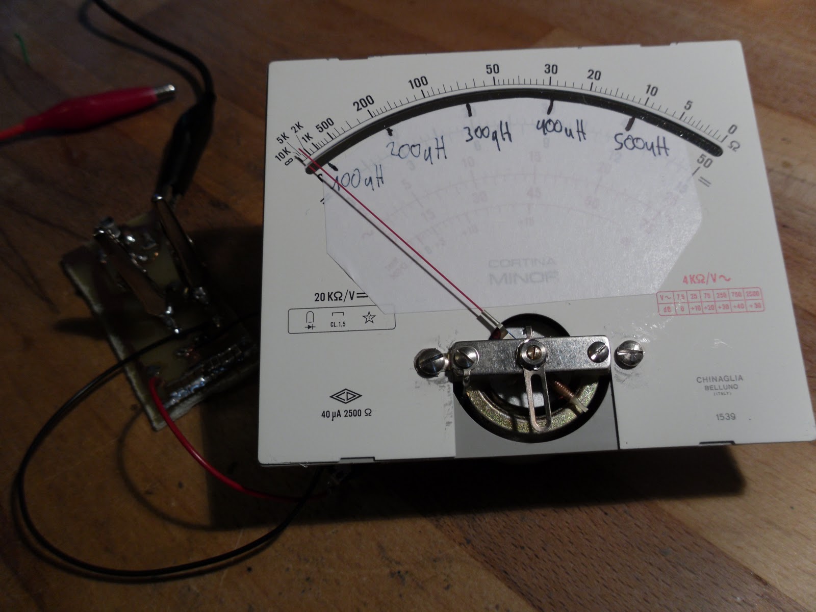
I "recycled" an old analog multimeter to get a nice µA-meter:
So, this is how it looks like with everything on it:
Now, testing time!
The inductivity used is this one:
How do you like it?
I think it's a cool little gadget, saving time and money!
You can download the LTSpice file here.
Have a good time!
apexys
Hi there! it's time to review my newest gadget: the Android Epad 10.2"
As the name says, it is a iPad-clone with a slightly bigger screen (10.2") and running Android 2.1. Here is a image of how it looks like in the commercial:
And here is another image of it, take with my digital camera:
It is pretty hard to get it on camera, but this is, how the home screen looks like. The Epad has a 1GHz ARM processor like the iPad, but it has a resistive touchscreen with 1024x600 pixels resolution, but unlike the iPad, it can be used with a pen or gloves.
Here are some photos of the interfaces:
The internet connectivity is done via WiFi or an external USB surf stick. It has two gigabytes of internal NAND flash and can use TransFlash aka µSD cards. The PC data connection is done with a mini-USB cable, here called OTG. You can charge the internal LiIon accumulator by applying 9VDC to the DC-terminal or simply using the included charger. I was surprised by the rather high audio quality of the 3.5 mm output, even though the internal speakers are crap. You can connect it to a LAN with the included adapter, which looks like this:
The operating system is Android 2.1. I like it, being small and fast. It loads almost every website, even though it can't do every kind of script. You can use it to view videos on YouTube, to watch DVDs (even via an external USB DVD drive!) or blogging on BlogSpot, as I'm doing now.
The virtual keyboard is a bit hard to use (You have to leave your hand some milimeters above the touchscreen and pull down the fingers separately), but you can use an USB keyboard. If you want to exchange data without using a mini-USB cable, just do it using a µSD card.
Some applications some exist in the Android Market, some you have to code on your own. But hey, the Android SDK is free, so ain't it a great platform for mobile hacking? I just need a compiler that runs directly on it.
You can pick these tablets up on ebay for about 200€ for a brand-new one or find it for the same price in other internet stores. Finally, I would say, it's really a great gadget with much functionality for low price.
I hope you liked this review! /apexys/01312011/1921
Hi!
This time it's a small piece of software, I've written to simplify the programming of timers in an AVR.
Many people, especially beginners or people who come from the Arduino corner dislike the timers due to their complexity. But it's really not that hard.
With a scientific calculator and a sheet of paper, you can easily set them.
And now I wrote this program, which replaces calculator and paper!
It looks like this:
It was written in VisualBasic, even though I like C# better.
I used VisualBasicExpressEdition to design the form.
You can download the source code and compiled program here.
/apexys/01202011/1521
Here is a small, but fine compilation of my first self programmed computer games.
All of them are done in Visual Basic .NET.
I was 12 years old when I did them!
1. Hübbie Shooter
A small, but for a first game quite good game.
All you have to do is to "shoot" the flying birds with your mouse.
It uses about 50 different PictureBoxes which are made visible and invisible by a timer. Sorry, but this game is just available in German.
Here is a screenshot:
2. Go!
Go is a Space Invaders clone.
You are the blue box and must shoot the red box.
Left shift is the "laser cannon" and left ctrl is the "guided missile".
This was my first game that used a non static surface.
It might not look so nice as Hübbie Shooter, but its much more fun!
Look:
And again a circuit with my favourite IC: the NE555!
Here is my version of the soft blinker:
You see right, there is no preresistor for the LED, due to the extremly high base resistor of the transistor!
Here is how much current flows through the LED:
The current is between 2 and 5 milliamps, so you could also connect an npn-transistor to drive whole arrays with it.
It is not a sine wave, but a sawtooth.
But hey, it's a soft blinker with a NE555!
Here is a video I took of my prototype.
While playing around with 150 relays, I built a full adder.
I managed to get it down to 9 relays (closing type) and some diodes.
Here is the schematic:
Please note that relay 6 is just a drawing error, due to the diode near the closer of relay 8 it's unnecessary.
The Resistors are all 1k, which seems to be an appropriate value for my 24V/2.7kOhms relays, but maybe you need to change it depending on your relays.
The diode near the sum output might be useless, but I need more time to test it.
This all is not tested yet, it's just an idea I wanted to share.
In my piezo fluid analyzer,
I used the piezo-stripe uncoated.
It seems like a small layer of metal is peeled off by the ultrasonic vibrations.
After half an hour in cream soap, a brown isolating layer had been exposed.
I think I'll try a thin coating around the piezo stripe.
Here comes my newest experiment:
A NE555 based analyzer for fluids.
It's basic task is to differ between different types of fluids like water, cream soap and so on based on their viscosity.
The basic idea is the following:
I encapsulate some liquid in a box with some kind of slider like this:
If I move the Slider like this
the fluid would move like that:
So if I use a constant velocity to move the slider,
I'll have to use a differing force based on the friction, which is defined by the viscosity.
Now my idea was to use a piezo stripe and a constant frequency.
The piezo would be the slider and the constant frequency would have the effect of a constant velocity.
Gone through all this, I built a small circuit with the NE555, a piezo stripe which I cut from a piezo speaker and a plastic box.
Here is the schematic:
I used one multimeter to measure the current through the piezo and another one to measure the system voltage.
The voltage defines the strength that the slider moves with.
Here is some data:
Tested object
Current(5V)
Current(10V)
Water
9mA
22mA
Ethanol
7mA
18mA
Cream Soap
10mA
30mA
All aquired at 19°C room temperature. with a 1.8 x 4 cm piezo stripe.
You can see easily the differences in viscosity between the fluid.
Ethanol has a rather high viscosity, so it takes little strength to move the slider.
Cream Soap is - like the name says - a cream and has a rather low viscosity.
How could I use this thing?
Well, in this configuration, it can differ between cream soap and water.
It's not everything, but hey, a proof of concept.
If you calibrate it and build a mechanical more stable version, you could use it to make automatic quality controls on your cream soap or such.
You could build one in SMT into a glass to measure if it contains beer or cola (or cream soap ;-).
Let's see what future will give us...
Hi and a happy new year.
My blog 2.0 goes into the new year with some experiments.
It's nice and calm in the time between the years, so don't expect big thing.
I'll rather do some experimenting with some physic things like densitiy, light spectrums, ...
The first thing will be the viscosity analyzer.
Well, then a happy new year!
\apexys\toan\01012011\2035


